Friday, October 30, 2020
Thursday, December 24, 2015
Christiansen Classic Arcade


After my 1st Raspberry Pi Project (The Photo Frame), I decided to attempt to make a "RetroPie Arcade." I first heard about this project towards the end of April, and in October decided to look more into making one. I gave myself a finish date for Christmas, and would give it to the kids. After all, aren't the best gifts hand-made?
On Christmas Eve 2015, we gave the arcade to the kids. Here's them playing it for the first time!
_____________________________________________________
I've put some of the photos and time-lapse videos on this post. They're in reverse-chronological order, starting with the most recent video.
By this time my little helper figured out what I was up to, so I decided to have him give it a test-drive. Keep in mind that he has never played Super Mario Brothers and is used to touching the screen.
After hot-gluing the T-Molding that wouldn't stay in place, I cut out the posters that I'd printed at Sam's Club to use on the sides of the cabinet. Once they were in place, I screwed in the bottom panel.
I put the monitor in place in this step using Velcro. I then caulked the edges (to give it a more finished look).
I put the marquee sign in place and attempted to put a screen over the monitor. I couldn't quite get the plastic screen over the monitor to work, so I decided to not use one.
 |
| AFTER zip-tying the button wires. |
 |
| The insides. |
I put the T-Molding, Joysticks and Buttons on in this step. While I remembered to label the "Player 2" up and down access points, I didn't for "Player 1." Because of this, I had to hook up the buttons and figure out which way was up.
In this step, I put primer on the cabinet, then painted it black. I originally purchased Black Spray Paint, but it was too cold to paint outside, so I painted in the basement. When the paint was dry, I put the piano hinge on the back access door and attached it to the cabinet.
Part of the project was to create a power switch that would turn on everything in the cabinet: the computer, the monitor, the speakers and the LEDs for the marquee. I'm a novice when it comes to electrical wiring, so I relied heavily on the Internet for wiring. Unfortunately the switch that I bought didn't come with any instructions. To add some complication, I bought a back-lit button that needed to be wired correctly as well. This button remains lit as long as there is power going to it. I tested it out in the kitchen on the outlet next to the sink. I did this because if there was a short, the outlet would trip and I could reset it easily.
I used a jigsaw to make the marquee frame, which will make the back-light marquee sign possible.
Because of my error from Day 1 of cutting the wood, I needed to have a Day 2. The cutting got easier as I went along, as I learned how to use the battery-powered circular saw more.
I used MDF (Medium Density Fiberboard) for the paneling of the arcade. This stirred up A LOT of dust, and if I ever make one of these again, I'll either use more expensive wood (The MDF board was 1/2 the cost of the next step up of wood) or make one in the summer when I can cut outside. Everything went well with the cutting right up until the last cut, where I cut the bottom piece the wrong end, so it would be shorter than 20 inches wide.
One of the challenges that I faced was how to attach the T-Molding. This is the flexable plastic that goes around the edges. Because I don't have a router or the router bit that I'd need, I tried to make the groove using a battery-powered circular saw. The trial worked, I'd just have to be a little more careful on the final project in getting a cut in the center.


I've downloaded a few games (28) and I tried out "Donkey Kong." There is no sound because I haven't attached the speakers yet.
Part of the project was to have a lit marquee sign above the screen. I tried this out on the prototype with an LED strip. I choose to back-light a print that I had printed at our local Sam's Club by sandwiching the "photo" in between two pieces of plastic. For the plastic I used a $5 frame from Wal-Mart and cut it to size.
After wiring the joysticks and buttons, I tested the control panel on my Windows computer. Posting this video proved to be helpful. It took me almost a month to realize that two of the buttons were always being "pressed," or in the "on" position. Once I realized this, it was a simple re-wiring of two buttons. The error that I was getting was that the start button on two-player games wouldn't work because the "start" and "insert coin" were constantly being pushed (or so it thought). .
I hooked up the wires to the controller (this is what tells the computer which button is being pressed). It didn't take very long. I first daisy-chained the ground then connected each of the buttons to the USB controller.
Because I still had some spare plywood laying around, I decided to attempt to make another control panel, this time with measurements that I plan on using in the final build (20 inches wide). Also, I'll be able to test the joystick and button functions with the Raspberry Pi.
I received the buttons and joysticks that I bought on eBay. My next step was to build a control panel to see if the buttons and joysticks work. In my attempt to assemble the control panel for the arcade, I realized that the buttons didn't fit because I used the wrong bit. After I used the correct bit, the joystick was too close to the buttons, and would not fit. My next attempt will be to make a wider control panel, allowing more room in between the joystick and buttons.
I was looking in the garage for some cardboard to tape together a simple prototype of the tabletop arcade. While searching for this, I noticed that we had some extra drop-ceiling panels in our garage. I had always thought that it was extra drywall, which would just crumble if I tried to piece it together. After cutting a sample of the ceiling panels (ironically with a drywall saw), I decided to use this instead of piecing together cardboard. The ceiling panels are also 1/2 inch thick, which is what the blueprints call for. I also used the time-lapse function of my camera to speed up the prototype-building process:
End of October - I searched locally on Craigslist for a 19-inch NON-widescreen monitor to use for this project, that I've now decided to tackle. The closest monitor under $50 was for $20 in North Prairie, WI (2 hours away). Coincidentally, my parents live in North Prairie. I emailed the seller and he had two monitors, so I offered $30 for both. The next day my dad picked up both monitors.
Mid-October - I sold two old Roku Boxes that were going to be out-of-support. I was looking at getting the new Roku 4 with the money that I sold them for, but decided to spend the eBay money on a bar-top arcade cabinet for the kids for Christmas. I found the detailed instructions on an instructable web site: Bartop Arcade Instructions. I downloaded the PDF that had the measurements for the front panel (which would hold the screen) and decided that the first thing (and hardest to find) would be an old monitor.
April 29th, 2015 I first heard about the arcade cabinet on TWIG (This week in Google). I thought that it would be a good idea to make for the kids.
Saturday, June 06, 2015
My Raspberry Pi Photo Frame Project
 |
| The Finished Project |

 |
| The Raspberry Pi with NOOBS (the little card) |
 |
| The 16:9 monitor |
The Raspberry Pi computer is cheap: $35.99, including an 8GB microSD card with adapter and NOOBS (The Operating System) pre-installed. As for a display panel, my dad gave me an old 16:9 computer monitor that he wasn't using anymore.
Once I got the monitor I realized that it didn't have an HDMI port on it, so I found an HDMI to DVI cable on Amazon for $6.99. In the same Amazon Prime shipment I added a $7.99 USB wi-fi adapter to pull images from the Internet without more wires. I already had a USB keyboard, mouse and USB power adapter with a micro USB cable, all required to get the computer up and running.
As for the actual photo frame itself, I had leftover baseboards that had been sitting in the garage since we've lived here that I thought would work. I looked into using posterboard as a matte, but I didn't have the tools to cut it. I ended up bringing the monitor into a craft store (40% off coupon in-hand) and had a matte board and glass cut for this project (~$25).
One of my goals for the display was to have it pull images from a photo set from flickr or another photo-sharing site. I found many resources, and used bits and pieces from a few different sites. The most useful site I referenced was found on instructables, written by Steven Landon. This gave a step-by-step guide on how to program the computer to run a media panel, which could pull photos from DropBox, 500px and flickr. This software also made it possible to specify a URL or upload a single photo to display. Another site I used was Making A Digital Picture Frame by Fredrik Hubbe, which leaded me in the right direction to make the frame for the panel. When I got stuck, I headed over the the raspberry pi forums and found some answers there.
Here are the steps that I used to complete my Raspberry Pi photo frame project:
1) The first thing I needed to do was set up the Raspberry Pi. Since I bought the computer kit with Raspbian pre-installed on a 8GB microSD card, I was able to configure it right away. After inserting the microSD card, connecting the monitor, plugging in the USB wi-fi dongle and bluetooth USB dongle, I plugged in the power and saw the "Raspberry Pi Software Configuration Tool." The changes I made were:
a. Expand the Filesystem
b. Change the Password
c. Enable Boot to Desktop
d. In Advanced Options, I changed my hostname so my network would recognize my Pi on the Network.
e. Then in Advanced Options, I enabled SSH so I can access my Pi from a computer on my network. f. Lastly, I selected finish which restarted my Pi.
2) Then I configured my wi-fi dongle to work with my wi-fi router by editing a file in the command-line terminal:
a. To edit the file, I typed in the terminal:
sudo nano /etc/wpa_supplicant/wpa_supplicant.conf
Then I made the file that was there look like this:
ctrl_interface=/var/run/wpa_supplicant
network={
proto=RSN
scan_ssid=1
key_mgmt=WPA-PSK
pairwise=CCMP TKIP
group=CCMP TKIP
ssid="your network ID in quote marks"
psk="your network password in quote marks"
}
update_config=1
b. To save the file I pressed ctrl + x, then Y to confirm, and then pressed Enter to save the edited file.
c. Then I restarted the Pi by entering:
sudo reboot
3. Once the Pi rebooted and I was connected to the Internet, it was time to update it to the latest software.
a. To get the latest updates, I entered the following command into the Terminal:
sudo apt-get update
Y to confirm and then Enter to get the updates.
b. Then, to get the upgrade, I entered:
sudo apt-get upgrade
Then I pressed Y and then Enter to install the upgrades (This took about 5 minutes to install)
4. Then I installed and configured a browser that would display the media panel properly.
a. To install the IceWeasel browser, I typed in the terminal:
sudo apt-get install iceweasel
b. Then I configured the IceWeasel browser to display the Media Panel:
i. I typed in about:config in the address field and then hit enter.
ii. Next I found the "browser.sessionstore.resume_from_crash" line and double clicked it to change it to false.
5. For the display panel to pull photos from flickr, I needed the browser to point to the website mPanel.
a. But first, I configured mpanel to work with my flickr account at:
http://designelemental.net/mpanel/
b. After I was done tweaking mpanel, I had to set IceWeasel's home page to mpanel by editing the preferences in the edit menu.
c. I then hit the F11 key to go full screen, then ctrl + Q to exit the browser.
d. I want IceWeasel to start automatically, so in the terminal I type:
sudo nano /etc/xdg/lxsession/LXDE/autostart
then, I add
@iceweasel
to the list, typed ctrl + X then Y and Enter to save the changes.
5. To have the mouse arrow disappear when not in use, I installed Unclutter by typing into the Terminal:
sudo apt-get install unclutter
6. I had some trouble getting the computer not to go to sleep after 10 minutes. I tried many different methods, and finally I found one that worked. I ended up installing a screensaver, enabling it, and then setting the screensaver never go to sleep by typing the following into the Terminal:
sudo apt-get install xscreensaver
Then, in the menu of xscreensaver, I clicked on Mode and then clicked "Disable Screen Saver."
Now that I had the Raspberry Pi up and running, I realized that there were significant "Black Bars" on the left and right sides, as well as the top and bottom of the monitor. Because it was using the DVI input, I could not change the size of the picture that was being displayed. I decided to use an older monitor than the one that was given to me, it was a 19 inch 4:3 aspect ratio monitor. When I hooked it up, the black bars were gone and the 4:3 aspect ratio is more like a typical photograph than a 16:9 display.
You're Done :D
Now it’s all setup you can plug it in to your wall mounted monitor and turn it all on.
If something stops working just unplug the pi then plug it back in, hey presto she starts again. Unfortunately my spare HDMI monitor does not have the screw holes for a wall mount bracket. I have decided to use an old VGA monitor I had laying around, just have to wait for the HDMI to VGA converter.
Building the frame:
I decided to not to take apart the monitor and use just the display for two reasons: If I used the monitor as-is, I could use a VESA mount to attach it to the wall and (2) I had never taken apart a monitor before, and really didn't want to make a mistake and ruin it.
Before starting on the frame, I went to a craft store to get glass and a matte cut. To do this, I brought the monitor in and had them cut a two inch matte around the 19 inch monitor, then a piece of glass was cut to match the outer edge of the matte.
I then got a four pack of flat corner braces, which came in a pack with screws (~$2 at Home Depot). As stated before, we already had the baseboards that were in the garage that I was going to use for the frame itself.
 |
| The Square |


After I drew the 45 degree angles, I measured and cut them using a hand-held battery-powered circular saw.


I then decided to "Screw It, Not Glue It." I used smaller screws to connect the corners, which resulted in a much sturdier frame. Then I used some 3M hanging hooks (the ones that are mostly used for hanging keys on the wall) to hold the matte and glass in place.


I cut some 1x3 inch wood to create brackets for the frame to attach to the monitor. The square foam tape seen in the photo is to raise the right side of the frame so it will be even on both sides.


Next I hung the monitor using a VESA mount from Amazon ($10). I first hung it in the garage before bringing it into the house to make sure everything was square and up-and-running.


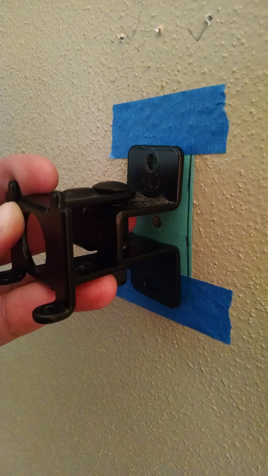


Then I realized that the middle of the VESA mount was NOT in the middle of the frame. I decided to use the old frame that I built as a template for where I should drill the holes in the living room. After finding the stud, I had Mandy tell me where she thought the frame should go, then I made a pencil mark in the middle of the hole and drilled some pilot holes where the mount was (with the aid of a Post-It note).

The VESA mount was square after I drilled into the wall.


The monitor after hanging it.


The hanging picture frame.


The photo frame after hooking up the Raspberry Pi.

My "setup" to try to fix the screensaver problem.


Now it was time to get rid of those hanging wires. I found an in-wall speaker cable kit a few months ago for $5. It included the drill bit, the pull-through system and some speaker wire (which I won't be using).


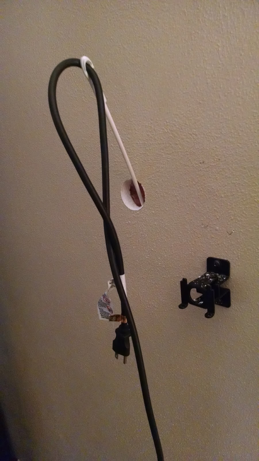


I then pulled the power cord through the wall and near an outlet.
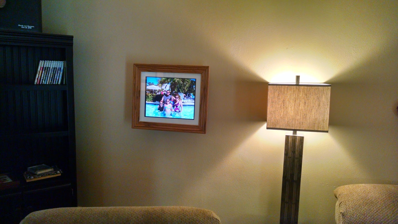
And that's it! The Raspberry Pi Photo Frame is complete (for now!) In the above photo, the frame is crooked. The mount from Amazon is fully articulating, so it's an easy 1 minute fix. I did find one problem: It needs to be turned on when someone's in the room, and off when nobody is (to save electricity). I think I found a solution for this, and I'll update when I've fixed it.
Subscribe to:
Posts (Atom)
-
 After my 1st Raspberry Pi Project (The Photo Frame), I decided to attempt to make a "RetroPie Arcade." I first heard ...
 -
 The Finished Project We recently got new furniture for our living room and I was looking for an electronic photo frame to fill the b...
